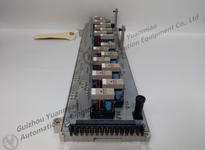
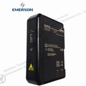
EMERSON 1C31223G01 Communication module
The timer in the PLC is equivalent to the time relay in the relay system. It has a set value register (one word long), a current value register (one word long) and an image register (one binary) to store its output contact status. The three storage units use the same part number. The timer of FX series PLC is divided into general timer and integral timer.
The constant K can be used as the setting value of the timer, or the contents of the data register (D) can be used to set the timer. For example, the data input by the external digital switch can be stored in the data register as the setting value of the timer. Data registers with backup batteries are usually used so that data will not be lost in case of power failure.
Number of timers and component numbers for each series. The time range of the 100ms timer is 0.1~3276.7s, and the time range of the 10ms timer is 0.01~327.67s. When the special auxiliary relay M8028 of FX1S is in 1 state, T32 ~ T62 (31 points) is defined as 10ms timer. When connecting the normally open contact of X0 in Figure 3 – 10, the current value counter of T200 starts from 0 and accumulates 10ms clock pulse. When the current value is equal to the set value 414, the normally open contact of the timer is connected, and the normally closed contact is disconnected, that is, the output contact of T200 drives 10ms in its coil × 414=4.14s。 After the normally open contact of X0 is disconnected, the timer resets, its normally open contact is disconnected, the normally closed contact is connected, and the current value returns to 0. 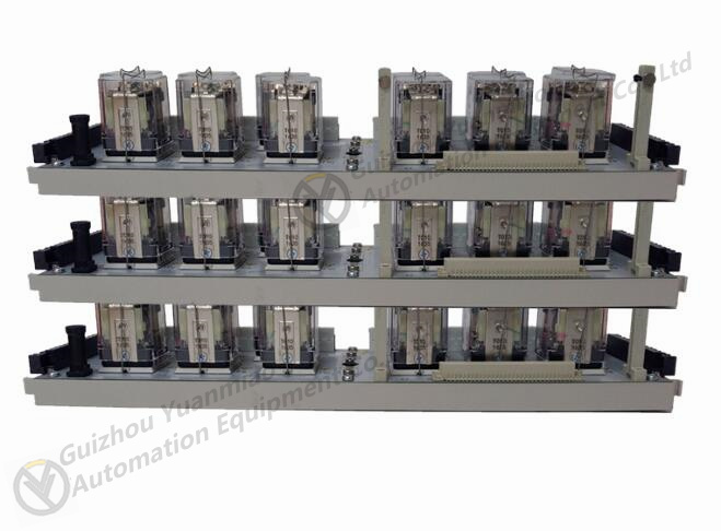
CPU module is equivalent to human brain and heart. It continuously collects input signals, executes user programs, and refreshes the output of the system; Memory is used to store programs and data.
CPU chip
CPU module is mainly composed of CPU chip and memory. The PLC uses the following types of CPU chips:
(1) General purpose microprocessors, such as Intel’s 808680186 to Pentium series chips;
(2) SCM, such as Intel’s MCS51/96 series SCM;
(3) Bit chip microprocessor, such as AMD2900 series bit chip microprocessor. storage
The memory of PLC is divided into system program memory and user program memory. The system program is equivalent to the operating system of the personal computer, which makes the PLC have basic intelligence and can complete various tasks designated by the PLC designer. The system program is designed by the PLC manufacturer and solidified in the ROM. The user cannot read directly. The user program of PLC is designed by the user, which determines the specific relationship between the input signal and output signal of PLC. The capacity of user program memory is usually in words (each word is composed of 16 binary digits). Mitsubishi’s FX series PLC calls the unit of user program storage step (i.e. word). The user program memory capacity of small PLC is about 1K words, and the user program memory capacity of large PLC can reach several M (megabytes) words.
———————————————————-
[Disclaimer]
Our company sells new products and discontinued products, and purchases such special products through independent channels. Guizhou Yuanmiao Automation Equipment Co., Ltd. is not an authorized distributor, distributor or representative of the featured products of this website. All product names/product images, trademarks, brands and microlabels used on this website are the property of their respective owners. Product descriptions, descriptions or sales with these name images, trademarks, brands and logos are for identification purposes only and do not represent any association or authorization with any right holders.

