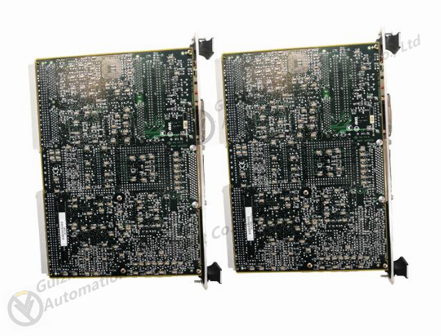
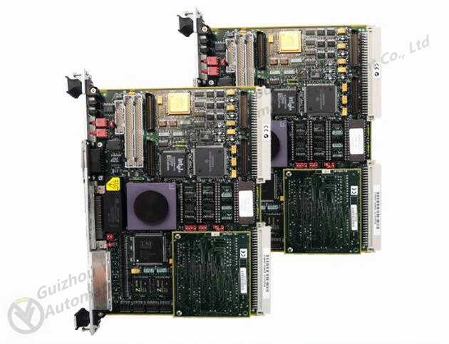
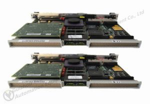
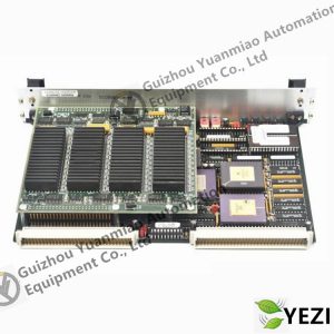
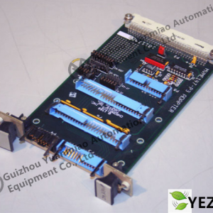
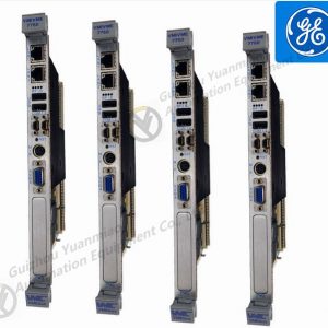
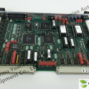
Motorola MVME162-213 VME board
MVME162-213 firmware must meet the requirements of testing and initialization and provide operating system boot support. The MVME5100 firmware monitors exceed the VME responsible requirements for these embedded system proven monitors. MVME162-213 extends the power on test and other functions of extensive diagnosis and powerful
Evaluation and debugging tools, Xu’s simple checkout or advanced development debugger require additional support. All these are included in the MVME5100 firmware; In addition, it supports starting the operating system and kernel. The operating system and core MVME5100 support the startup of various operating systems Motorola Built in Test (MBIT) is an off the shelf design to verify the correct operation of Motorola hardware, and throw it into system level diagnosis. A. The Comprehensive Donkey Manual for Software Development provides guidance on the CD-ROM of MBIT. Two versions of MBIT are available, Goose Wind is compatible with Tornado 2.1 of river system. MVME162-213 board level MBIT is a logical device installed on the board with diagnostic software packages used to verify performance. MVME162-213 All tests can be executed. When starting, the selected test can continuously run the background of the user application in. API includes operations for accessing test results and modifying and controlling device tests. MVME162-213 system level MBIT includes all functions and API function call board level versions and enables full system testing. The framework and other API functions supported by the system level MBIT include software, hardware and or system components for testing customization.
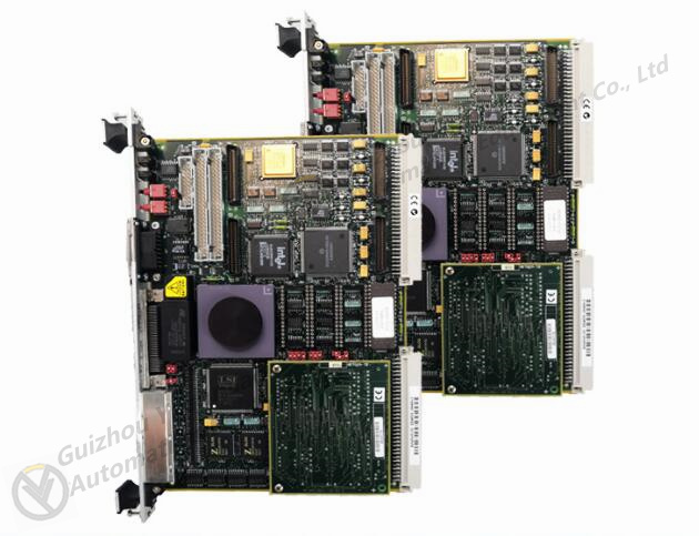
MVME162-213 Industrial Control Spare Parts DC S/PLC System Controller Card。
我司产品主要运用行业有:化工,汽车,火电,钢铁,塑胶,风电,
电厂、造纸、钢铁、矿场、橡胶、供水、水泥、化工、玻璃、印刷
纺织、机械、塑料、涂料、医药、医院、食品、宾馆、科研院校等
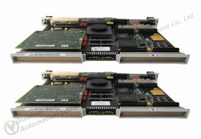
MVME162-223 module
After the PLC is put into operation, its working process is generally divided into three stages, namely input sampling, user program execution, and output refresh. Completing the above three stages is called a scanning cycle. During the entire operation period, the CPU of the PLC repeatedly executes the above three stages at a certain scanning speed.
Input sampling stage
During the input sampling phase,
The PLC sequentially reads in all input states and data in a scanning manner and stores them in the corresponding units in the I/0 image area. After the input sampling is completed, it enters the user program execution and output refresh phase. In these two stages, even if the input state and data change, the state and data of the corresponding units in the I/0 image area will not change. Therefore, if the input is a pulse signal, the width of the pulse signal is greater than one scanning cycle in order for the input to be read in under any circumstances.
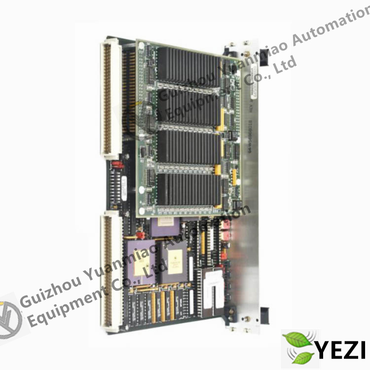
| MOTOROLA | MVME147-013 |
| MOTOROLA | MVME162-012 |
| MOTOROLA | MVME162-023A |
| MOTOROLA | MVME162-10 |
| MOTOROLA | MVME162-13 |
| MOTOROLA | MVME162-220 |
| MOTOROLA | MVME162-512 |
| MOTOROLA | MVME162-512A |
| MOTOROLA | MVME162-522A |
| MOTOROLA | MVME162-522A 01-W3960B/61C |
Disclaimer
Our company sells new products and discontinued products, and purchases these unique products through independent channels. Guizhou Yuanmiao Automation Equipment Co., Ltd. is not an authorized distributor, distributor, or representative of the featured products on this website. All product names/product images, trademarks, brands, and micro logos used on this website are the property of their respective owners. Product descriptions, descriptions, or sales with these name images, trademarks, brands, and logos are for identification purposes only and do not imply any association or authorization with any rights holders.

